
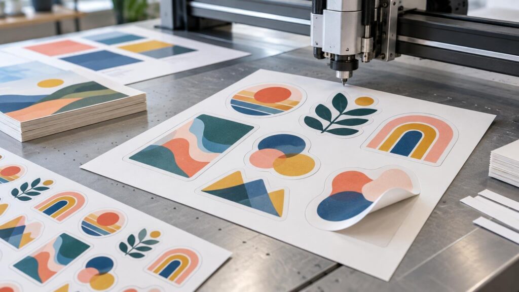
TLDR: Die cutting printing combines printed artwork with a finishing operation that cuts the piece to a custom outline or creates functional features such as holes, slots, folds, and perforations. “Die-cut” often describes the finished shape, not necessarily the machinery used. Production may involve a physical steel-rule die, a digital contour cutter, or a laser-based system. Buyers should concentrate on the required shape, material, quantity, tolerances, and approved proof rather than assuming one cutting technology is always best.
For stickers, labels, cards, invitations, hang tags, packaging components, and shaped promotional pieces, the practical question is not simply whether die cutting printing is available. It is whether the design can be printed, cut, stripped, handled, and delivered without fragile points, uneven borders, missing interior pieces, or important artwork landing too close to the edge.
What is die-cut printing?
Die-cut printing is a common buyer-facing name for printing followed by shape cutting. Printing creates the graphics; cutting converts the printed sheet, roll, or mounted material into the required outline. That makes cutting a finishing or converting operation, even when a provider presents printing and cutting as one product.
The term can cause confusion because “die-cut” is used in two ways. It can refer to a result—a sticker or card with a custom outline—or to a process that uses a manufactured physical die. A digitally contour-cut sticker may therefore be sold as a die-cut sticker even though no metal die was made for that order. Traditional steel-rule and digital cutting have different setup, throughput, flexibility, and material tradeoffs. The appropriate method depends on the job rather than the product name alone. Readers who want the production-level comparison can consult the Printing United Alliance discussion of traditional and digital die cutting.
This distinction matters commercially. A buyer requesting a “die-cut sticker” is usually specifying the finished format. A packaging buyer asking whether a quoted job uses a flatbed or rotary die may be investigating tooling cost, production speed, repeatability, scoring, stripping, or compatibility with a specific substrate.
The basic die-cut production workflow
Although equipment and sequence vary, most custom-shaped print projects move through four broad stages:
- Define the finished dimensions, material, printed design, cut outline, and any functional features such as folds, scores, holes, or perforations.
- Prepare and preflight the artwork, including bleed, safe space, image resolution, transparency, and a cut contour where the provider requires one.
- Print the artwork and align the cutting operation to the printed image using the production workflow’s registration system.
- Cut and finish the pieces, which may include removing surrounding waste, separating usable pieces, blanking carton components, counting, packing, or mounting stickers on a liner.
Flatbed, rotary, and laser-based cutting approaches all exist. Industrial converting lines may also incorporate stripping and blanking after the shape is cut. BOBST likewise documents flatbed and rotary converting systems used in print-and-die-cut applications for paperboard and cartons. These industrial distinctions matter for folding cartons and long runs, but a sticker buyer normally does not need to select a machine. The provider should choose a suitable process after seeing the material, geometry, quantity, and quality requirements.
Physical dies, digital cutters, and lasers compared
| Method | How it works | Usually attractive when | Important tradeoff |
|---|---|---|---|
| Physical steel-rule die | A shaped cutting rule is mounted in tooling and pressed through or into the material. | The shape will be repeated, production volume supports tooling, or the job needs integrated cutting and related converting operations. | Tooling adds setup and makes late shape revisions more consequential. |
| Digital contour cutting | A computer-controlled tool follows programmed paths without a shape-specific cutting die. | Quantities are shorter, designs change frequently, or multiple custom outlines must be produced flexibly. | Throughput and suitable materials depend on the cutter, tool, geometry, and production workflow. |
| Laser cutting | A focused laser follows a programmed path and removes material with heat. | Tool-free cutting or intricate programmed geometry suits the approved substrate and application. | Heat can limit suitable substrates or alter an edge, so material compatibility must be confirmed. |
These are categories, not promises of identical results. A physical die may be flatbed or rotary. A digital system may use a drag knife, oscillating knife, routing tool, or another tool selected for the material. Laser cutting is also digital in the broad sense, but it behaves differently because heat is involved; published industry guidance notes that this creates substrate limitations.
Method selection should account for quantity, substrate, thickness, edge expectations, shape complexity, revision risk, finishing sequence, and provider capabilities. A tool-free process can reduce the burden of making a unique physical die, but “no die” does not mean “no setup.” The cut file still requires preparation, nesting, registration, machine setup, inspection, and waste handling.
Die-cut stickers, kiss-cut stickers, and sticker sheets
Sticker terminology describes both how deeply the material is cut and how the finished stickers are supplied. Confirm the delivered format instead of relying on “custom cut” as a complete specification.
| Format | What is cut | How it is supplied | Useful for |
|---|---|---|---|
| Individual die-cut sticker | The sticker face and backing are cut around the custom outer shape. | As separate individual pieces. | Handouts, package inserts, event distribution, and merchandise. |
| Kiss-cut sticker | The face material is cut while the backing liner remains available around or behind it. | On a larger backing piece that can be easier to peel or carry. | Detailed outlines, branded backing areas, and convenient peeling. |
| Sticker sheet | Multiple sticker faces are cut on one shared liner. | As a sheet containing several stickers or designs. | Sticker packs, planner sets, product kits, and grouped illustrations. |
Printiverse distinguishes individual die-cut stickers from sticker sheets and describes a custom cut-path and proof workflow. Current formats and ordering requirements should be checked on the custom sticker printing page before artwork is finalized. Buyers comparing another source for custom-shaped stickers should still confirm whether the quoted product arrives as loose pieces, kiss-cut pieces on individual backers, or multiple designs on a shared sheet.
How to prepare artwork for die cutting printing
Good cutting begins with an unambiguous finished shape. The printer must know what belongs to the printed image, what extends beyond the trim, and which path represents the intended cut. Use the provider’s product template whenever one exists; a generic setup rule should not override a product-specific template or reviewed proof.
Set the artwork at final size
Create the document at the intended finished dimensions rather than expecting production to infer scale. If the artwork will be enlarged, raster images can lose usable detail. Printiverse’s general artwork guidance recommends final-size artwork and 300 DPI for image-based files, while also addressing bleed, safe space, transparency, and cut-line handling. The complete artwork and file setup guide provides the current starting point for submitted files.
Extend edge-to-edge artwork into bleed
Bleed is extra printed image extending beyond the final cut. It prevents a slight cutting or registration variation from exposing an unintended unprinted sliver. Printiverse identifies 0.125 inch as a common starting point for flat pieces, but the applicable product template or proof controls when its requirement differs. Do not add an arbitrary bleed value after the provider has supplied a specific template.
Keep critical details inside a safe area
Safe area is the space between critical content and the expected cut. Text, logos, faces, QR codes, borders, and other elements that must remain intact should not crowd the cut path. Bleed protects the outer edge; safe space protects important content on the inside. They solve opposite sides of the same tolerance problem.
Use a clear cut contour
A cut contour is commonly represented as a vector path because a vector line can define geometry independently of image resolution. Providers may require that path on a separate layer, under a designated spot-color name, or in a production template. Others may create the contour from uploaded artwork and show it in the proof. Follow the product’s current instructions rather than assuming every printer uses the same naming convention.
Vector artwork is helpful but not always mandatory. A high-resolution PNG with a transparent background may provide enough information for a provider to construct a contour, while a JPG has no transparency and may leave the intended boundary unclear. The real requirement is an identifiable shape plus enough image quality for the printed size. Ask whether production will create the cut line and whether that service changes cost or timing.
Why intricate shapes create tolerance problems
No printing and cutting workflow has mathematically perfect registration on every piece. The practical goal is a controlled result within the provider’s production tolerance. The design should make small variation difficult to notice rather than turning it into a visible defect.
Thin points, tight inward corners, tiny holes, narrow gaps, detached islands, and highly irregular outlines can create production or handling problems. A shape might be technically cuttable but still peel poorly, bend in packing, trap waste, tear at a narrow connection, or produce an edge that dominates the artwork.
Fragile geometry can often be improved by simplifying the contour:
- Round extremely sharp exterior points where the design permits.
- Widen narrow bridges connecting one part of the shape to another.
- Remove tiny notches that contribute little to the recognizable silhouette.
- Avoid small disconnected pieces unless the chosen format is designed to retain them on a common liner.
- Move text and other critical details farther from irregular cut sections.
- Use a deliberate border or offset around complex artwork rather than tracing every pixel-level detail.
Borders deserve particular attention. A narrow border makes normal positional variation conspicuous because one side may appear thicker than another. Either allow enough width for the expected tolerance or use full-bleed artwork that does not depend on a perfectly even frame.
What affects die-cutting cost?
Cost is driven by the whole production plan, not just the perimeter length. Relevant factors can include quantity, substrate, finished size, sheet utilization, tooling, number of unique shapes, cut complexity, machine time, waste removal, scoring or perforating, packing, and the likelihood of repeat orders.
A physical die creates an upfront tooling consideration, but it may make sense when the same design will run at sufficient volume or be reordered. Digital cutting avoids shape-specific die manufacture and makes revisions easier, but machine time remains real. Complex paths can take longer to process than simple shapes, while many disconnected internal areas may increase waste-removal labor.
To compare quotations fairly, give each provider the same finished size, quantity, material, number of designs, cut geometry, backing or sheet format, finishing requirements, delivery destination, and deadline. A low printed unit price is not comparable if another quote includes contour setup, tooling, proofing, stripping, or individual packing.
Review the proof as a production instruction
A proof is not only a spelling check. For custom-shaped work, it communicates how the printer understands the relationship between the artwork and cut. Review it at a useful scale and inspect the entire perimeter rather than checking only the center graphic.
- Confirm the finished dimensions and orientation.
- Trace the proposed cut outline visually from start to finish.
- Check that full-bleed color extends beyond the cut.
- Verify that text, logos, faces, and codes have comfortable clearance.
- Look for thin points, tight corners, tiny islands, and unwanted interior holes.
- Confirm whether transparent areas are truly transparent rather than white.
- Inspect borders for sufficient width and intentional alignment.
- Confirm whether stickers arrive individually, on separate backers, or on sheets.
- Check all folds, scores, holes, slots, and perforations when the product includes them.
- Verify quantity, material, finish, and any packing requirements separately from the artwork.
If the cut path is not visible or its meaning is unclear, do not approve by assumption. Ask whether the displayed line is the actual production contour, a safety guide, or only a preview boundary. Approval should represent agreement on both the printed appearance and the finished shape.
The practical ordering takeaway
Specify the result first: finished dimensions, material, quantity, individual or sheet format, outer contour, and any functional cuts. Then ask the provider to confirm the production method only when that method changes tooling cost, revision flexibility, substrate compatibility, edge appearance, or schedule.
For designers, the safest handoff is final-size artwork with adequate image resolution, product-specific bleed, protected critical content, and a clearly understood cut contour. For buyers, the most important control is the proof. Approve it only after checking the shape, border treatment, transparency, safe area, delivery format, and all finishing features. That is how a custom outline becomes a controlled commercial-print specification rather than an ambiguous request to “cut around the logo.”